Saving batteries life of an electric garland.
Posted on April 07, 2024 in Hardware
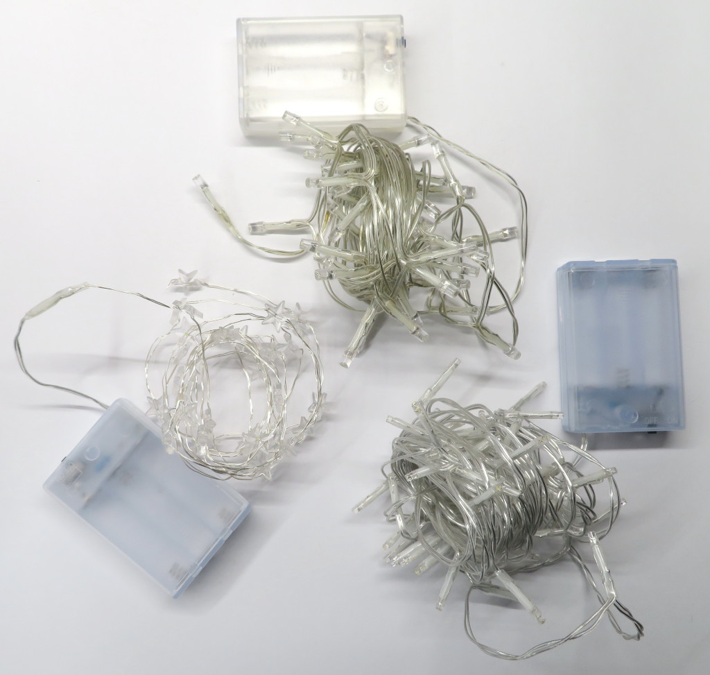
3 diferent guarlands.
To get an idea of what could be done to improve battery life, we need to understand what we're dealing with.
First, the schematic. It's important, because the possible actions depend on its structure. All the garlands I'm interested in for this project have the same basic layout.
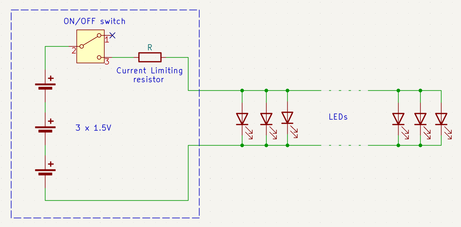
Garland Schematics.
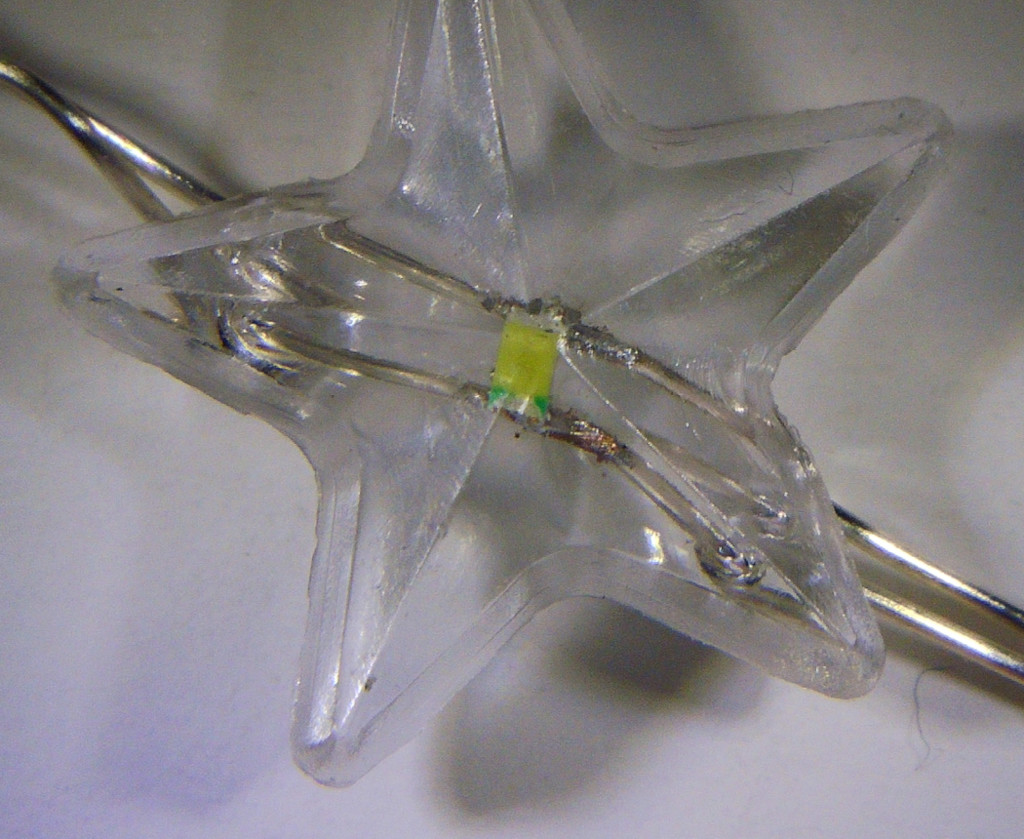
LED soldered directly onto wires (front and rear view).
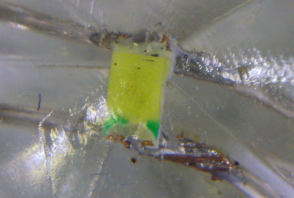
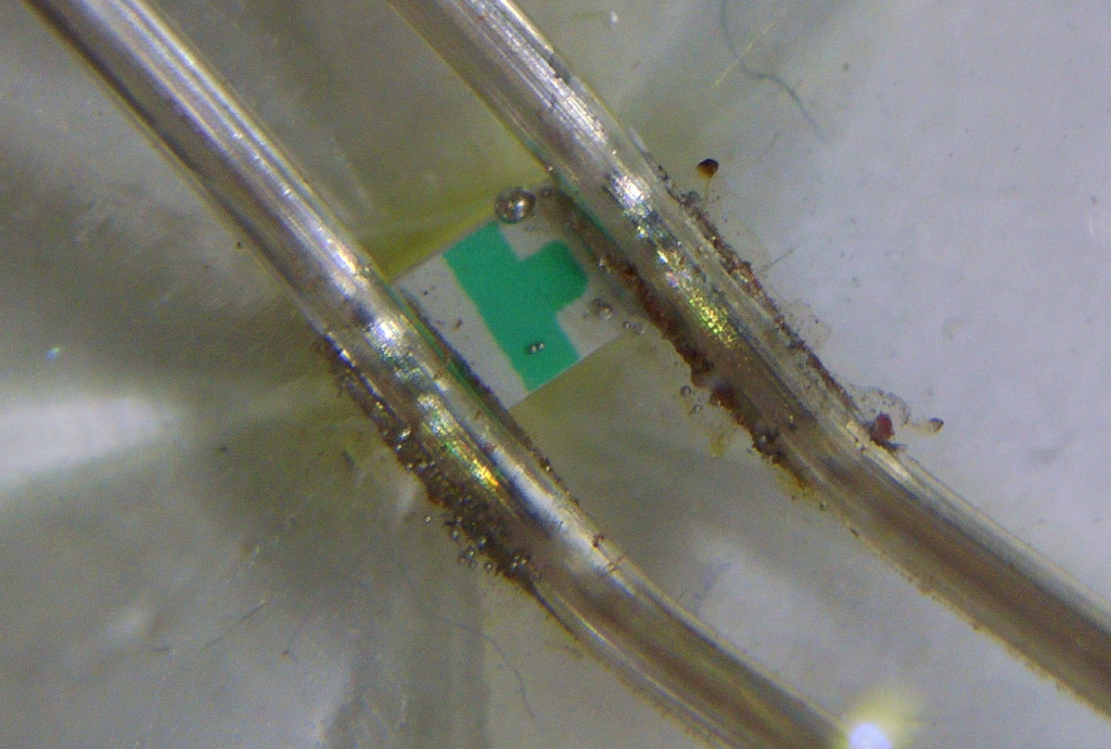
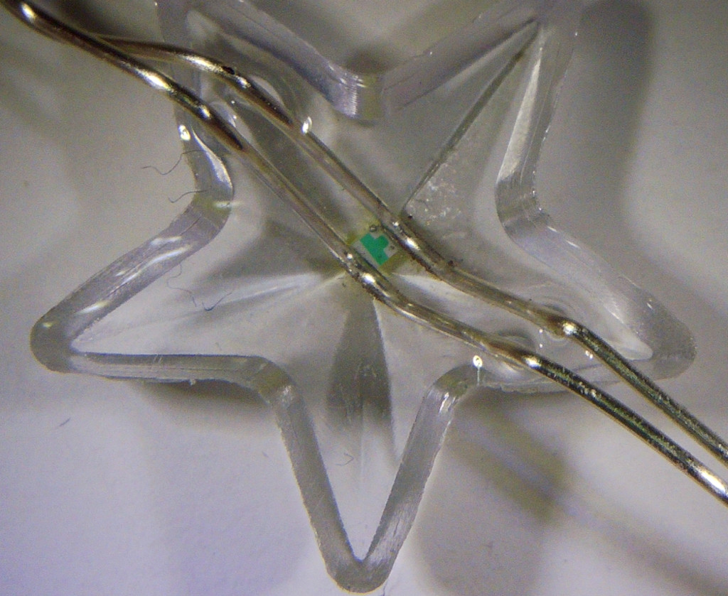
Zoom in on the welds (not very clean).
As the batteries voltage is not regulated, overall current is dependent on batteries condition. Of course, it will be higher with new batteries than with old ones. But how much does the overall current vary?
To find out, I took some readings on 3 different garlands.
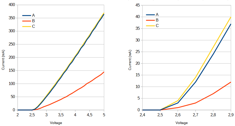
Current/Voltage curves for the 3 guarlands (details on the right).
The curves show a zero current below 2.5V. This is not the case. The measurements were made using the built-in meter on my lab power supply which has a resolution of 1mA. It is therefore impossible to know the current below 2.5V with this measurement method. But it wouldn't make any difference, as brightness is very low below 1mA.
With new batteries, I've found that the garlands light up far too brightly, which is confirmed by the high current consumption. I've also found that just a few milliamps are needed to achieve the right brightness.
From these observations and the preceding curves, we can conclude that 2 points of action are possible:
- Limit the voltage applied to the garland to limit the current flowing through it.
- Operate the garland with the lowest possible battery voltage to extract more energy from the batteries.
The brightness of an LED depends directly on its current. So, the brightness of a garland depends on the current flowing through each LED in the garland.
The ideal operating current is not fixed. It depends on the garland, the lighting environment and the user's preferences. After testing, for the A string, the current is between 12mA and 24mA. For garland B, it's between 7mA and 12mA. And for garland C, between 14mA and 27mA. These are estimates, of course, but the important thing to remember is that the current must be adjustable.
Ideally, the LEDs should be driven by a current generator. But that's not possible here. As garlands are very simple and inexpensive products all the LEDs are soldered in parallel, and a simple resistor acts as a global current limiter. So we need to create a voltage generator, not a current generator.
For the currents we're interested in, the corresponding voltage is around 2.8V (see current/voltage curves). When the batteries are new, their voltage is around 4.8V. This is well above the determined value. As we saw in point 2, it would be interesting to be able to operate the garland with the lowest possible battery voltage.
We therefore need a Buck-Boost voltage regulator capable of delivering a fixed voltage with an input voltage lower than, equal to or higher than its output voltage. This regulator must be able to deliver a few tens of milliamps at output. It must also be very small, as space is at a premium. The voltage of the 3 batteries does not exceed 5V, an important parameter when choosing the regulator.
For the regulator, I chose the STBB1 from ST Microelectronics. This component accepts input voltages from 2V to 5.5V. It therefore supports 3 new 1.5V batteries (approx. 3 x 1.6V = 4.8V) and extracts maximum energy from the batteries (up to 0.66V per battery).
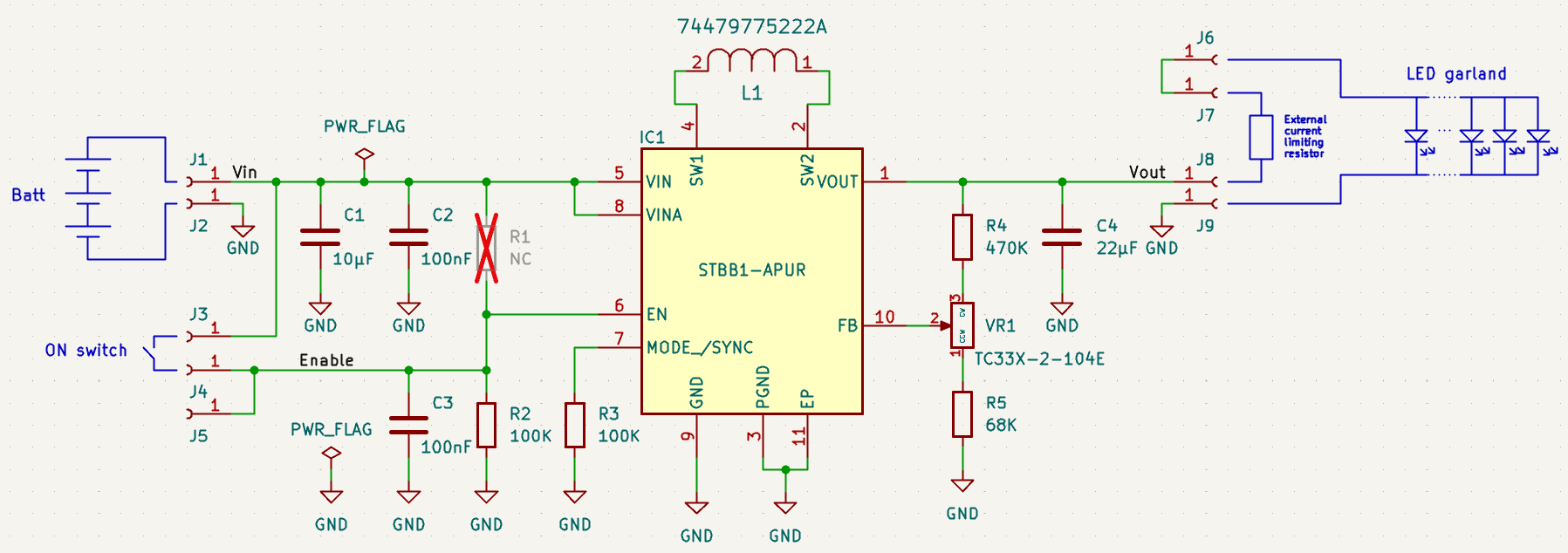
Board schematics.
- The circuit can be wired in 2 different ways.
- The switch on the battery box switches the regulator power supply. In this case, resistor R1 (100k) must be wired, but not R2 or C3.
- The switch on the battery box switches the regulator's enable, which is permanently powered. In this case, resistor R1 is not wired. R2 and C3 form a filter that suppresses glitches in the "Enable" signal. In fact, the switches mounted on garlands housings are low-end and often have false contacts that make the garlands "sizzle". Note: The fact that the regulator is permanently powered is not a problem, since it consumes very low power when in 'shutdown' mode (<1µA).
The printed circuit board is shaped to fit the garland battery box.
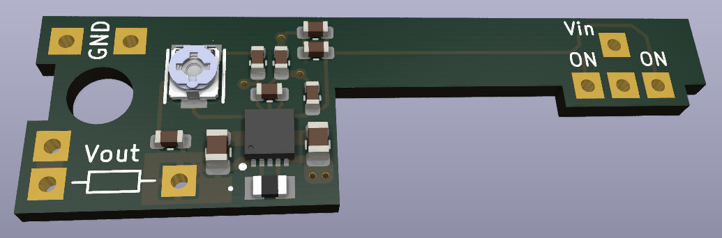
3D view of the PCB.
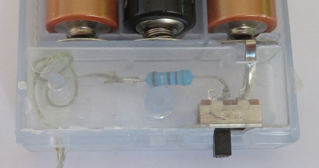
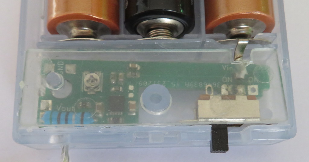
A battery box before and after modification.
For the output voltage adjustment, the potentiometer I've chosen is not insulated (metal case). As the adjustment slider is directly connected to the regulator's feeback pin regulator, it's important to use an insulated screwdriver. I used the one I use to adjust the probe compensation on my oscilloscope.
The system works well, but to my surprise, when the batteries run down, the garland starts flashing at a very low frequency. I expected it to "sizzle" but, in fact, it flashes at a frequency that depends on the output voltage, battery wear, battery type, temperature...
In the example below, the garland lights up for a few hundred milliseconds over a period of several seconds.
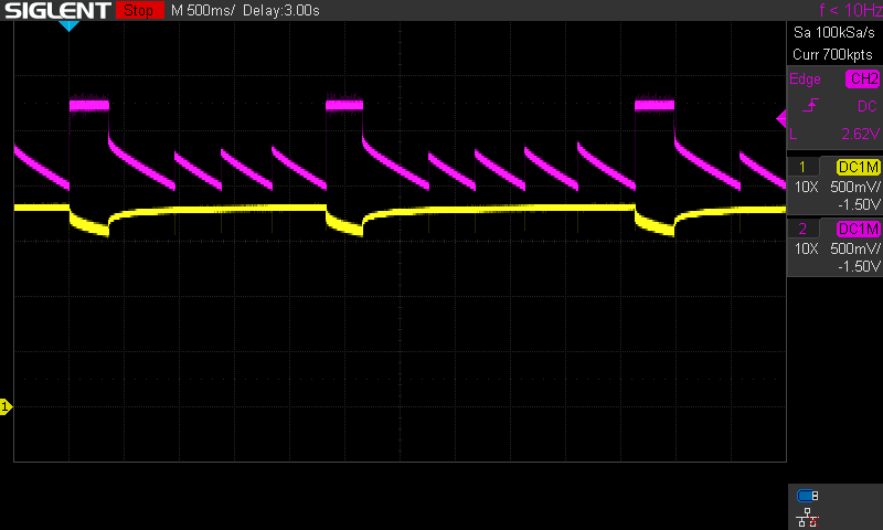
Flashing when batteries are flat.
The battery voltage is in yellow. The regulator ouput voltage is in magenta.
A closer look reveals that the regulator stalls below a certain battery voltage. As the regulator no longer consumes energy, the battery voltage rises slowly. The regulator makes several failed attempts to restart until the battery voltage is high enough to restart. As the controller consumes energy again, the battery voltage drops until the regulator stalls again. And the cycle starts all over again...
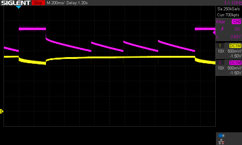
Zoom in on the flashing cycle.
In conclusion, this electronics brings 2 improvements.
- A constant, adjustable garland brightness.
- An extended battery life.
The second point is difficult to quantify. It depends on the garland, the batteries and, above all, the brightness selected by the user.
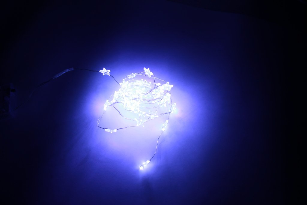

Brightness with fresh batteries (left) and with flat batteries (right).
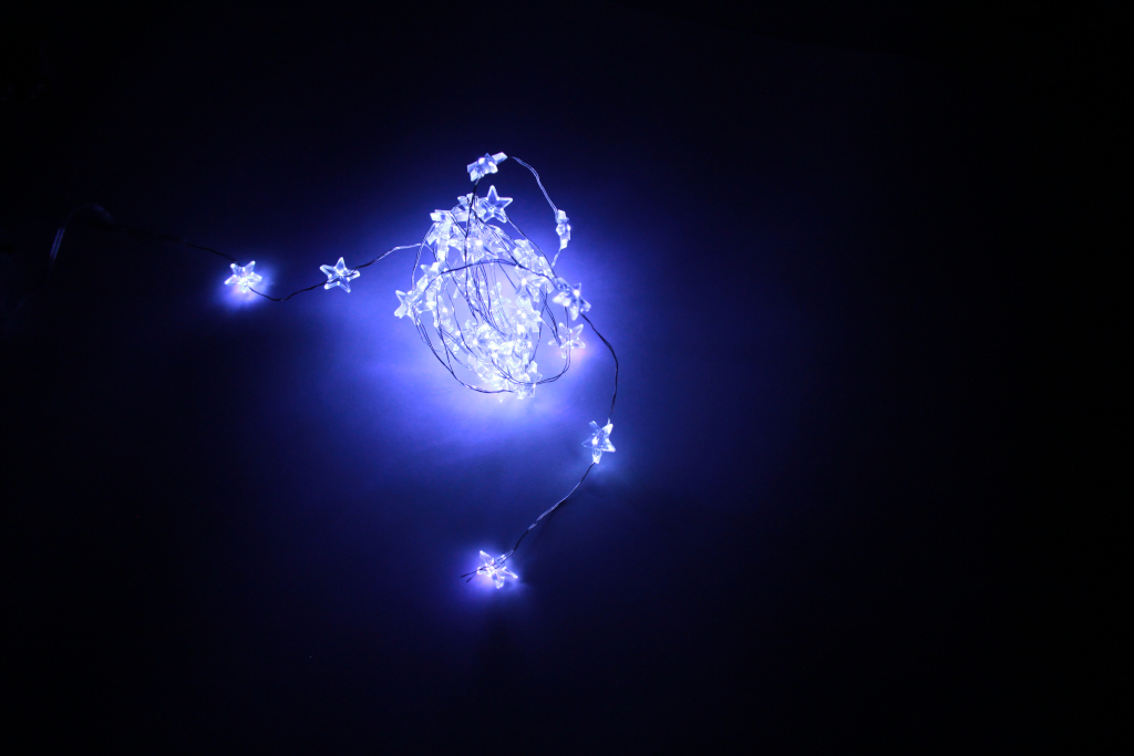
Brightness with control electronics installed and set.